Unfortunately I can’t find any libraries and templates that follow this use case. Was this removed recently? Is there anything similar that’s available?
Does this exist somewhere? Is it in development or maybe it was scrapped?
Screenshots (in case the page gets removed):
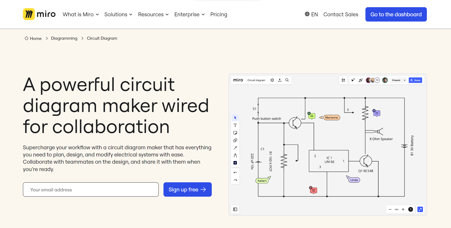
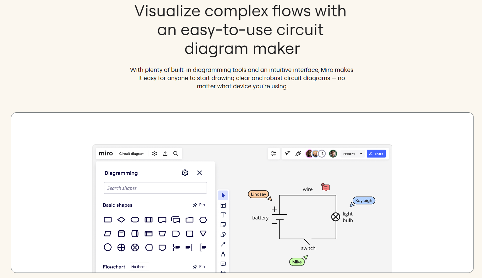
The fact that the above screenshot does not actually show a “Circuits shapes” pack on the left is leading me to believe this could have been a misleading marketing campaign, suggesting that you could just go find some circuit diagramming images on the Internet, upload them into Miro, and use connection lines to make diagrams. The screenshot does show the “summing junction” diagram shape being used, but there is no “switch” or “battery” icon that I can find anywhere. And recreating those would be a mix of text and connection lines.
Does this exist somewhere? Is it in development or maybe it was scrapped?
Screenshots (in case the page gets removed):
The fact that the above screenshot does not actually show a “Circuits shapes” pack on the left is leading me to believe this could have been a misleading marketing campaign, suggesting that you could just go find some circuit diagramming images on the Internet, upload them into Miro, and use connection lines to make diagrams. The screenshot does show the “summing junction” diagram shape being used, but there is no “switch” or “battery” icon that I can find anywhere. And recreating those would be a mix of text and connection lines.
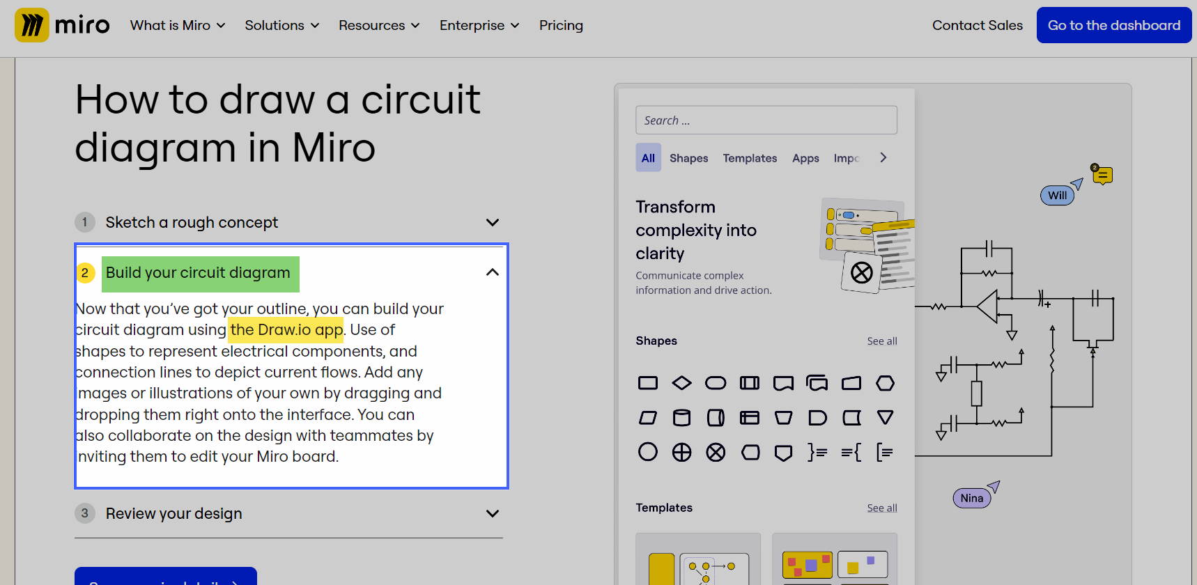
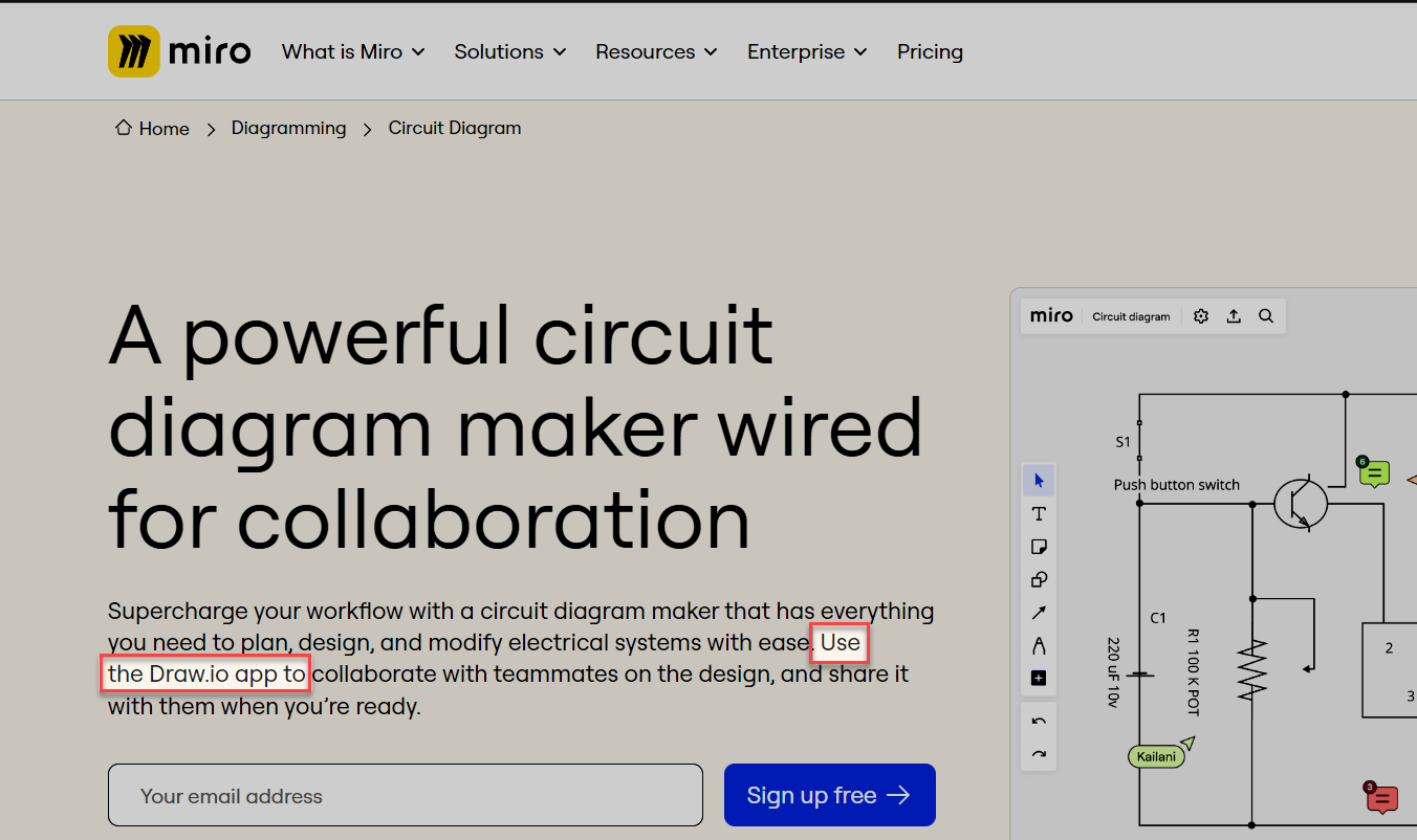
@kurisu - The support team has responded that they have reached out to the product team for a definitive answer, but did directly me to this blurb, way down the page, inside of a collapsible/accordion, which appears to indicate that electrical diagraming in Miro can be done using the Miro Draw.io app:
I suspect the product team will confirm this, so I will continue to report back.
I am mildly disappointed that the Draw.io app is likely the answer as the Draw.io app doesn’t provide the same real-time collaboration experience that Miro itself does. For example, when multiple users are on the board, when someone opens a Draw.io created-diagram using the Draw.io app, the diagram becomes locked (similar to when a user is editing a sticky note). And while the non-editors on the board can eventually see the updates as the editor is making them, the editor is no longer able to see the board as the Draw.io app has opened up to fill the entire screen. So, if one of the non-editors says, I don’t agree with “x”, the editor cannot see what they may be pointing to with their cursor – or least that is how the Draw.io app experience is for me during my testing using two different accounts, from two different computers to simulate two users on the board at the same time.
@Robert Johnson thank you very much for taking all the effort to look into this.
And I see that the link to the “circuit diagram” the webpage has been taken down (404 error) haha.
I have to say that I’m a bit disappointed that this is through a third party app, although I do like draw.io and have used it extensively in the past. As you mentioned, the real-time collaboration aspect was what drew me to Miro and if I can do that with the technical drawings I work on with my colleagues, Miro would have been fantastic. The screenshots indicate such an experience but if I cannot see what my colleagues are pointing out as I’m editing the diagram via the draw.io plugin, then the point is moot. Even more so if my colleagues cannot participate in editing the diagram together in real-time.
Anyway, thank you very much. Still trying to find the right tool. I don’t need a full blown “circuit editing” tool, I have engineering software to do that, but they don’t make beautiful, simplified schematics that I need to make for presentations and publications. Just something with Miro’s collaboration features, a way to make a library of circuit symbols (which I can edit/update later and all my designs see these updates accordingly), with excellent grid snapping behavior and convenient ways of drawing the connectivity between elements.
You know this is disappointing in that for all the great things Miro does, electrical diagraming seems like something that would be right up their alley! Draw.io isn’t the best and it’s not as simplified and finding a decent basic electrical diagraming tool is harder than it sounds.
I use Miro for a lot of things and working at home on an electrical motor I came here thinking it would be a slam dunk for me to map it out in Miro but then finding Miro defers this to a more clunky workflow than it uses natively.
Would like to see something done in-house for things like this because it really is a slam-dunk if Miro would develop even a very basic electrical schematic icon pack.
Thank you for sharing your thoughts on this! We appreciate your feedback.
If having an in-house electrical schematic tool or icon pack in Miro would be beneficial for you, we encourage you to submit this as a wishlist idea. Our product team actively reviews these suggestions and considers them for future updates.